niedziela, 18 września 2016

New antenna rotator controller on Arduino

During last IARU contest my rotator suddenly refused to work in one direction. So going right was done electrically and going left - manually - run to the antenna, rotate manually, run to the station.

Maybe this mode is good for health and fit but definitely does not improve station's results... Plan for this year is to repair the rotator but I was thinking already to replace the current steering device with something more advanced.

At least I would like to see direction of the antenna on some kind of map...

Currently the N1MM shows the arrow and digitally direction but not on any kind of map.

I found a project which looks promising and may be base for really good solution:


The whole project is described here:

http://100nf.blogspot.ch/2016/06/arduino-mega2560-based-antenna-rotator.html

My plan would be:

  • use the Arduino mainboard and LCD color touch screen
  • build computer interface with one of the common standards of antenna rotators protocols (supported by N1MM logging software)
  • use relay module to steer the engine. I have seen modules with 4 relays - maybe it could be also possible to use one of relays to switch on/off the 24V converter (it produces loud RF noise and can be powered only when needed). In such case separate power would need to be provided for the main unit.
  • the rotator could be powered from 12/24V or via USB.
Now discussing details with Piotr SP8QEP who is Arduino expert .

Update from a few hours later...


  • Atmega 2560 with LCD and relays box ordered


poniedziałek, 5 września 2016

SX-28 further inspections


Some day had some spare time (why it happens so rarely... :)) and decided to have a closer look into the new SX-28 (new in my shack, it is nearly 70 years old and is probably the oldest thing in my home....)

Disassembling is not very difficult task - if you remember the weight around 20kg :)

Inside I found some work that needs to be done. 
The capacitors in the power supply look newer than 70 years but not sure. Were they blue in that time?


Transformers don't look new but luckily seem to work correctly.


Most of paper capacitors are wet and covered with oil.


Chassis is mostly in a very good condition - probably radio has been stored in dry and nice conditions.


Variable capacitors don't look too good. This is a problem because probably it will be difficult to find similarly mounted ones.


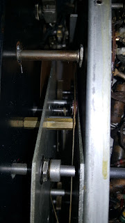
Elements are mounted in "3D" mode (not on PCB) - it will be very difficult to replace some elements. In the worst case I will have to dissasemble everything and build back using new elements.


Some potenciometers required cleaning.


VFO section from the top. Tubes belong to VFA, mixer and IF amplifiers.


I had some problems to find out how tuning works. Usually could not find a proper frequency. I have measured the VFO frequency and now I know how it works. In fact it is not as bad as I was afraid - I have to set the main dial to the "dot" on the scale and then the secondary dial shows more or less correct freq. Not bad...


Finally I have prepared list of elements I want to replace and slowly starting looking for them...